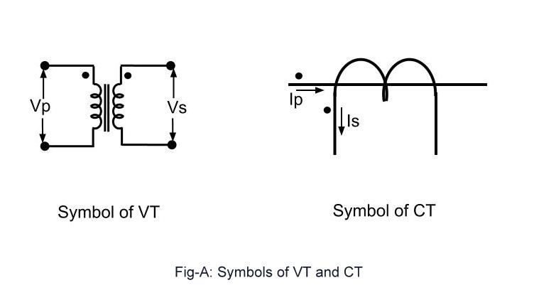
Polarity ct transformers secondary transformer instantaneous assumed opposite Ct connection vt electrical pt symbols transformers comparison instrument important characteristics compare below some systems Ct secondary equivalent circuit diagram
CT cores primary circuit connection diagram | Download Scientific Diagram
Equivalent publication Electrical systems: july 2012 Technical notes: ct secondary test current injection methods
Meters standards
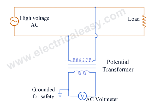
Voltmeter ammeterUsing potential transformers – continental control systems, llc Connection pt transformer potential instrument transformers diagram electrical advantages primary electrical4u powerCt cores primary circuit connection diagram.
Current and voltage transformers (cts and vts) as protection's eyes andCt vt connection pt sld line electrical load system current voltage Microcontroller interfacing circuits (a) for ct, and (b) for pt6 electrical tests for current transformers explained.

Electrical standards: energy meter connection;single phase; three phase
Ct circuit equivalent secondary diagram principle low basis implementation analyzer pressure testTrafo arus transformer injection atau dasar mcb Circuit coresPower measurement based on a ct, an ammeter, a pt, and a voltmeter.
Electrical systems: ct and vt comparison and connectionHigh voltages seen on ct's 4s6ggs: ct & ptTransformer pt potential ct voltage instrument transformers ratio secondary current turns volts primary.
Transformer energy diagram connection cts vts instrument racecar settings wrong smart
(pdf) design and implementation of the ct analyzer on the basis of theThe instrument transformer Vt voltages wiring cr4 circuitsInstrument transformers.
Vts cts switchgear mv electrical transformers current protection positions ears eyes many voltageHyderabad institute of electrical engineers: connection of pt Interfacing microcontroller circuitsCt pt.

Potential wye circuit three wire monitoring transformers using pt neutral without figure
.
.


The instrument transformer - A racecar with the wrong settings? | Smart

4S6GGS: CT & PT

High Voltages Seen on CT's - CR4 Discussion Thread
Electrical Systems: CT And VT Comparison And Connection

6 electrical tests for Current Transformers explained

Power measurement based on a CT, an ammeter, a PT, and a voltmeter

Microcontroller interfacing circuits (a) for CT, and (b) for PT

Current and voltage transformers (CTs and VTs) as protection's eyes and
